Intersection of a ray and a plane

I previously showed the derivation of how to determine the intersection of a plane and a cone. At the time I had to solve that equation, so after doing so I decided to publish it for anyone to use. Given the positive feedback, it seems this was useful, so I might as well continue with a few more.

Here is probably the most basic intersection: a ray and a plane. Solving it is straightforward, which I hope can be seen below. Like last time, I am using vector notation.

  1. We define a ray with its origin $O$ and its direction as a unit vector $\hat{D}$.
    Any point $X$ on the ray at a signed distance $t$ from the origin of the ray verifies: $\vec{X} = \vec{O} + t\vec{D}$.
    When $t$ is positive $X$ is in the direction of the ray, and when $t$ is negative $X$ is in the opposite direction.
  2. We define a plane with a point $S$ on that plane and the normal unit vector $\hat{N}$, perpendicular to the plane.
    The distance between any point $X$ and the plane is $d = \lvert (\vec{X} – \vec{S}) \cdot \vec{N} \rvert$. If this equality is not obvious for you, you can think of it as the distance between $X$ and $S$ along the $\vec{N}$ direction. When $d=0$, it means $X$ is on the plane itself.
  3. We define $P$ the intersection or the ray and the plane, and which we are interested in finding.
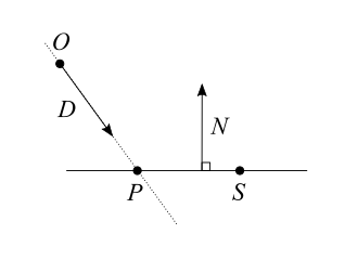
Since $P$ is both on the ray and on the plane, we can write: $$ \left\{ \begin{array}{l} \vec{P}=\vec{O} + t\vec{D} \\ \lvert (\vec{P} – \vec{S}) \cdot \vec{N} \rvert = 0 \end{array} \right. $$ Because the distance $d$ from the plane is $0$, the absolute value is irrelevant here. We can just write: $$ \left\{ \begin{array}{l} \vec{P}=\vec{O} + t\vec{D} \\
(\vec{P} – \vec{S}) \cdot \vec{N} = 0 \end{array} \right. $$ All we have to do is replace $P$ with $\vec{O} + t\vec{D}$ in the second equation, and reorder the terms to get $t$ on one side.
$$ (\vec{O} + t\vec{D} – \vec{S}) \cdot \vec{N} = 0 $$ $$ \vec{O} \cdot \vec{N} + t\vec{D} \cdot \vec{N} – \vec{S} \cdot \vec{N} = 0 $$ $$ t\vec{D} \cdot \vec{N} = \vec{S} \cdot \vec{N} – \vec{O} \cdot \vec{N} $$ $$ t = \frac{(\vec{S} – \vec{O}) \cdot \vec{N}}{ \vec{D} \cdot \vec{N} } $$

A question to ask ourselves is: what about the division by $0$? Looking at the diagram, we can see that $\vec{D} \cdot \vec{N} = 0$ means the ray is parallel to the plane, and there is no solution unless $O$ is already on the plane. Otherwise, the ray intersects the plane for the value of $t$ written above. That’s it, we’re done.

Note: There are several, equivalent, ways of representing a plane. If your plane is not defined by a point $S$ and a normal vector $\hat{N}$, but rather with a distance to the origin $s$ and a normal vector $\hat{N}$, you can notice that $s = \vec{S} \cdot \vec{N}$ and simplify the result above, which becomes: $$ t = \frac{s – \vec{O} \cdot \vec{N}}{ \vec{D} \cdot \vec{N} } $$


Signed distance to a plane

For the sake of simplicity, in the above we defined the distance to the plane as an absolute value. It is possible however to define it as a signed value: $d = (\vec{X} – \vec{S}) \cdot \vec{N}$. In this case $d>0$ means $X$ is somewhere on the side of the plane pointed by $\vec{N}$, while $d<0$ means $X$ is on the opposite side of the plane.

Distances that can be negative are called signed distances, and they are a foundation of Signed Distance Fields (SDF).

From Maxwell’s equations to Fresnel’s equations

This series of short videos shows how to derive Maxwell’s equations all the way to Fresnel’s equations. Each one is about 10 to 15mn long.

The first four videos show how to use boundary conditions to deduce the relationship between the electromagnetic field on both sides of a surface (or interface between two different media).

The next four videos use the previous results to obtain the Fresnel equations, for S-polarized and P-polarized cases.

The rest of the series then dives into other topics like thin film interference.

The series assumes the viewer to be already familiar with the Maxwell equations, so it can be helpful to first see the explanation by Grant Sanderson of 3Blue1Brown on Maxwell’s equations.

Intersection of a ray and a cone

Some time ago I needed to solve analytically the intersection of a ray and a cone. I was surprised to see that there are not that many resources available; there are some, but not nearly as many as on the intersection of a ray and a sphere for example. Add to it that they all use their own notation and that I lack math exercise, after a bit of browsing I decided I needed to write a proof by myself to get a good grasp of the result.

So here goes, the solution to the intersection of a ray and a cone, in vector notation.

  1. We define a ray with its origin $O$ and its direction as a unit vector $\hat{D}$.
    Any point $X$ on the ray at a signed distance $t$ from the origin of the ray verifies: $\vec{X} = \vec{O} + t\vec{D}$.
    When $t$ is positive $X$ is in the direction of the ray, and when $t$ is negative $X$ is in the opposite direction.
  2. We define a cone with its tip $C$, its axis as a unit vector $\hat{V}$ in the direction of increasing radius, and $\theta$ the half angle between the axis and the surface.
    Any point $X$ on the cone verifies: $(\vec{X} – \vec{C}) \cdot \vec{V} = \lVert \vec{X} – \vec{C} \rVert \cos\theta$
  3. Finally we define $P$ the intersection or the ray and the cone, and which we are interested in finding.

$P$ verifies both equations, so we can write:

$$
\left\{
\begin{array}{l}
\vec{P}=\vec{O} + t\vec{D} \\
\frac{ \vec{P} – \vec{C} }{\lVert \vec{P} – \vec{C} \rVert} \vec{V} = \cos\theta
\end{array}
\right.
$$

We can multiply the second equation by itself to work with it, then reorder things a bit.

$$
\left\{
\begin{array}{l}
\vec{P}=\vec{O} + t\vec{D} \\
\frac{ ((\vec{P} – \vec{C}) \cdot \vec{V})^2 }{ (\vec{P} – \vec{C}) \cdot (\vec{P} – \vec{C}) } = \cos^2\theta
\end{array}
\right.
$$

$$
\left\{
\begin{array}{l}
\vec{P}=\vec{O} + t\vec{D} \\
((\vec{P} – \vec{C}) \cdot \vec{V})^2 – (\vec{P} – \vec{C}) \cdot (\vec{P} – \vec{C}) \cos^2\theta = 0
\end{array}
\right.
$$

Remember the mouthful earlier about $\hat{V}$ being in the direction of increasing radius? By elevating $\cos\theta$ to square, we’re making negative values of $\cos$ positive: values of $\theta$ beyond 90° become indistinguishable from values below 90°. This has the side effect of turning it into the equation of not one, but two cones sharing the same axis, tip and angle, but in opposite directions. We’ll fix that later.

We replace $\vec{P}$ with $\vec{O} + t\vec{D}$ and work the equation until we get a good old quadratic function that we can solve.

$$
\require{cancel}
((\vec{O} + t\vec{D} – \vec{C})\cdot\vec{V})^2 – (\vec{O} + t\vec{D} – \vec{C}) \cdot (\vec{O} + t\vec{D} – \vec{C}) \cos^2\theta = 0
$$

$$
((t\vec{D} + \vec{CO})\cdot\vec{V})^2 – (t\vec{D} + \vec{CO}) \cdot (t\vec{D} + \vec{CO}) \cos^2\theta = 0
$$

$$
(t\vec{D}\cdot\vec{V} + \vec{CO}\cdot\vec{V})^2 – (t^2\cancel{\vec{D}\cdot\vec{D}} + 2t\vec{D}\cdot\vec{CO} + \vec{CO}\cdot\vec{CO}) \cos^2\theta = 0
$$

$$
(t^2(\vec{D}\cdot\vec{V})^2 + 2t(\vec{D}\cdot\vec{V})(\vec{CO}\cdot\vec{V}) + (\vec{CO}\cdot\vec{V})^2) – (t^2 + 2t\vec{D}\cdot\vec{CO} + \vec{CO}\cdot\vec{CO}) \cos^2\theta = 0
$$

$$
t^2(\vec{D}\cdot\vec{V})^2
+ 2t(\vec{D}\cdot\vec{V})(\vec{CO}\cdot\vec{V})
+ (\vec{CO}\cdot\vec{V})^2
– t^2\cos^2\theta
– 2t\vec{D}\cdot\vec{CO}\cos^2\theta
– \vec{CO}\cdot\vec{CO}\cos^2\theta
= 0
$$

Reorder a bit:

$$
t^2((\vec{D}\cdot\vec{V})^2 – \cos^2\theta)
+ 2t((\vec{D}\cdot\vec{V})(\vec{CO}\cdot\vec{V}) – \vec{D}\cdot\vec{CO}\cos^2\theta)
+ (\vec{CO}\cdot\vec{V})^2 – \vec{CO}\cdot\vec{CO}\cos^2\theta
= 0
$$

There we go, we have our $at^2 + bt + c = 0$ equation, with:

$$
\left\{
\begin{array}{l}
a = (\vec{D}\cdot\vec{V})^2 – \cos^2\theta \\
b = 2\Big((\vec{D}\cdot\vec{V})(\vec{CO}\cdot\vec{V}) – \vec{D}\cdot\vec{CO}\cos^2\theta\Big) \\
c = (\vec{CO}\cdot\vec{V})^2 – \vec{CO}\cdot\vec{CO}\cos^2\theta
\end{array}
\right.
$$

From there, you know the drill: calculate the determinant $\Delta = b^2 – 4ac$ then depending on its value:

  • If $\Delta < 0$, the ray is not intersecting the cone.
  • If $\Delta = 0$, the ray is intersecting the cone once at $t = \frac{-b}{2a}$.
  • If $\Delta > 0$, the ray is intersecting the cone twice, at $t_1 = \frac{-b – \sqrt{\Delta}}{2a}$ and $t_2 = \frac{-b + \sqrt{\Delta}}{2a}$.

But wait! We don’t have one cone but two, so we have to reject solutions that intersect with the shadow cone. $P$ must still verify $\frac{ \vec{P} – \vec{C} }{\lVert \vec{P} – \vec{C} \rVert} \vec{V} = \cos\theta$, or simply, if $\theta < 90°$: $(\vec{P} – \vec{C})\cdot\vec{V} > 0$.

Note that there is also the corner case of the ray tangent to the cone and having an infinity of solutions to consider. I’ve completely swept it under the rug since it doesn’t matter in the context I was, but if it does to you, you’ve been warned about it. Also remember to check the sign of $t$ to know whether $P$ is in the direction of the ray. You may need to determine which of $t_1$ or $t_2$ you want to use, which depends on your use case. For example is your ray origin inside or outside of the cone?


Now for a little sanity test, let’s consider the corner case $C=O$, where the ray origin is the tip of the cone (thanks Rubix for the suggestion!). We have $b=0$ and $c=0$ thus $\Delta=0$ and $t=\frac{-b}{2a}=0$ which is the expected result.

I also tried the cases $\theta=0$ and $\theta=\pi/2$, but expanding $\Delta$ proved too tedious to proceed to the end. So this is left as an exercise, as they say. :)


Finally, to demonstrate that the result is indeed correct, here is a glorious ray traced cone scene on ShaderToy:

I hope this can prove useful to others too.

Oh, and Happy New Year by the way!

Matrix and Quaternion FAQ

Although its caveats, a classic on the web and still a useful resource, here is the most recent version I found of the: Matrix and Quaternion FAQ.

Warning: the document I’m linking here has been orphaned for many years and might still contain errors. Moreover, the links are broken on this version hosted on Java 3D (they’re not on the even older, Princeton version).

Understanding quaternions

Quaternion are a very useful tool in 3D, but also one that is unintuitive and difficult to get a natural feeling about. The talk Jim Van Verth, of EssentialMath, gave earlier at GDC2013 explains some facts about quaternions and how they work, by looking back at their discovery: Understand Quaternions.

Update: on a side note, here is a trick for faster quaternion – vector multiplication.

Readings on vector class optimization

Now that Revision has passed, we feel tempted to grab the ax and happily chop into parts of our code base we wanted to change but couldn’t really since we had other priorities. One tempting part is the linear algebra one: vector, quaternion and matrix data structures. Lets say vector for a start. Not that it’s really necessary, but the transformations are the most time consuming parts after the rendering itself, and the problem itself is somewhat interesting.

After a little googling, I basically found three approaches to this problem:

Every here and there, people seem to think of SSE instructions as a silver bullet and propose various examples of code, snippets or full implementations. The idea being to use dedicated processor instructions to apply operations on four components at a time instead of one after another.

Quite on the opposite, Fabian Giesen argued some years ago that it was not such a good idea. A quick look at the recently publicly released Farbrausch codebase shows they indeed used purely conventional C++ code for it.

At last this quite dated article (with regards to hardware evolution) by Tomas Arce takes a completely orthogonal approach, consisting of using C++ templates to evaluate a full expression component after component, thus avoiding wasting time moving and copying things around.

I am curious to implement and compare them on nowadays hardware.


Update: this is 2016 and the topic was brought back recently when someone wrote the article How to write a math library in 2016.

The point of the article is that the old advice to not bother with SSE and stick with floats doesn’t apply anymore, and it goes on to show results and sample code. This sparked a few discussions on Twitter, with opinions voiced to put it mildly.

It seemed the consensus was still against the use of SSE for the following reasons:

  • Implementation is tedious.
  • For 3 dimensional vector, which is the most common case, there is a 25% waste.
  • For 4 dimensional vectors, like homogeneous coordinates and RGBA, it doesn’t work so well either since the fourth component is treated differently than the other ones.
  • Even if the implementation detail is hidden behind a nice interface, the alignment requirements will leak and become constraints to the rest of the code.
  • Compilers like clang are smart enough to generate SSE code from usual float operations.