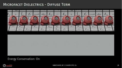
The white furnace test is one of my favourite rendering debug tools. But before it was so, it was rather mysterious and abstract to me. Why would a publication proudly show what seemed like empty renders? What does it mean, and why would they care?

Revisiting Physically Based Shading at Imageworks, presented at the SIGGRAPH 2017 course: Physically Based Shading in Theory and Practice.
The idea is the following: if you have a 100% reflective object that is lit by a uniform environment, it becomes indistinguishable from the environment. It doesn’t matter if the object is matte or mirror like, or anything in between: it just “disappears”.
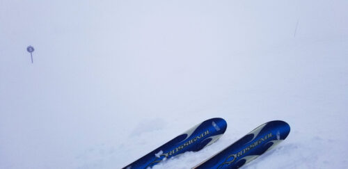
Accepting this idea took me a while, but there is a real-life situation in which you can experience this effect. Fresh snow can have an albedo as high as 90% to 98%, i.e. nearly perfect white. Associated with overcast weather or fog, it can sometimes appear featureless and become completely indistinguishable from the sky, to the point you’re left with skiing by feel because you can’t even tell the slope two steps in front of you. Everything is just a uniform white in all directions: the whiteout.

With the knowledge that a 100% reflective object is supposed to look invisible when uniformly lit, verifying that it does is a good sanity test for a physically based renderer, and the reason why you sometimes see those curious illustrations in publications. It’s showing that the math checks out.
Those tests are usually intended to verify that a BRDF is energy preserving: making sure that it is not losing or adding energy. A typical topic for example is making sure materials don’t look darker as roughness increases and inter-reflections become too significant to be neglected. Missing energy is not the only concern though, and a grey environment (as opposed to a white one) is convenient as any excess of reflected energy will appear brighter than it.
But verifying the energy conservation of a BRDF is just one of the cases where the white furnace test is useful. Since a Lambertian BRDF with an albedo of 100% is perfectly energy preserving and completely trivial to implement, the white furnace test with such a white Lambert material can be used to reveal bugs in the renderer implementation itself.
There are so many aspects of the implementation that can go wrong: the sampling distribution, the proper weighting of the samples, a mistake in the PDF, a pi or a 2 factor forgotten somewhere… Those errors tend to be subtle and can result in a render that still looks reasonable. Nothing looks more like a correct shading than a slightly incorrect one.
So when I’m either writing a path tracer or one of its variants, or generating a pre-convolved environment map, or trying different sampling distributions, my first sanity check is to make sure it passes the white furnace test with a pure white Lambertian BRDF. Once that is done (and as writing the demonstration shader above showed me once again, that can take a few iterations), I can have confidence in my implementation and test the BRDF themselves.
Take away: the white furnace test is a very useful debugging tool to validate both the integration part and the BRDF part of your rendering.
Update: A comment on Hacker News mentioned that it would be useful to see an example of what failing the test looks like. So I’ve added a macro SIMULATE_INCORRECT_INTEGRATION in the shader above, to introduce a “bug”, the kind like forgetting that the integration over an hemisphere amounts to 2Pi or forgetting to take the sampling distribution into account for example. When the “bug” is active, the sphere becomes visible because it doesn’t reflect the correct amount of energy.
